The terms get used loosely, and the usual explanation — that power
transformers are simply the big ones — is not quite right. It is close enough
to sound reasonable and wrong often enough to cause a bad specification.
The real distinction is duty: where the unit sits in the network, and how
it is loaded across a day.
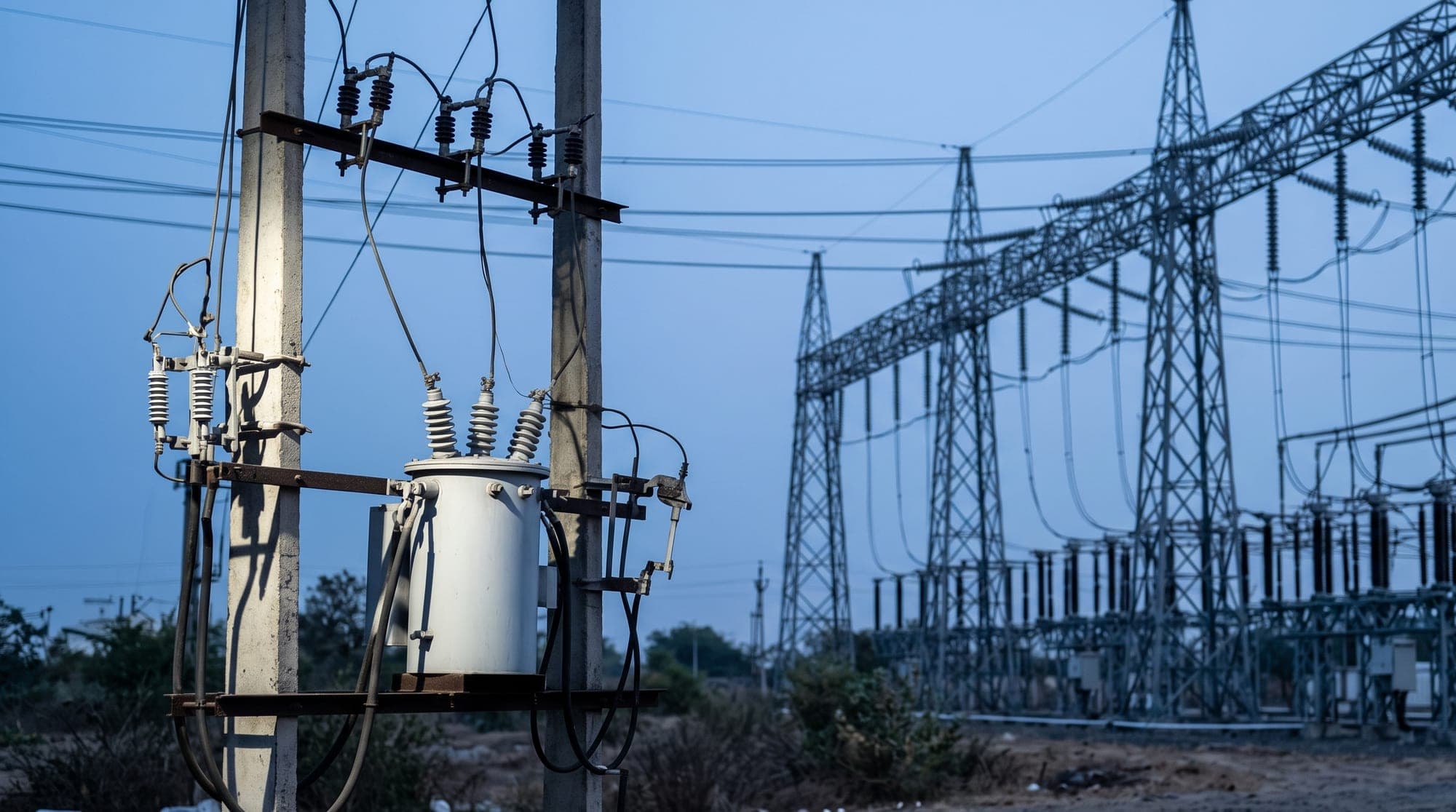
A distribution transformer is the last transformation before the load. It
sits on a pole, a plinth or in a small substation, and it feeds final
consumers — houses, shops, a small works. Its load varies continuously and
unpredictably, and for a large part of every day it is lightly loaded.
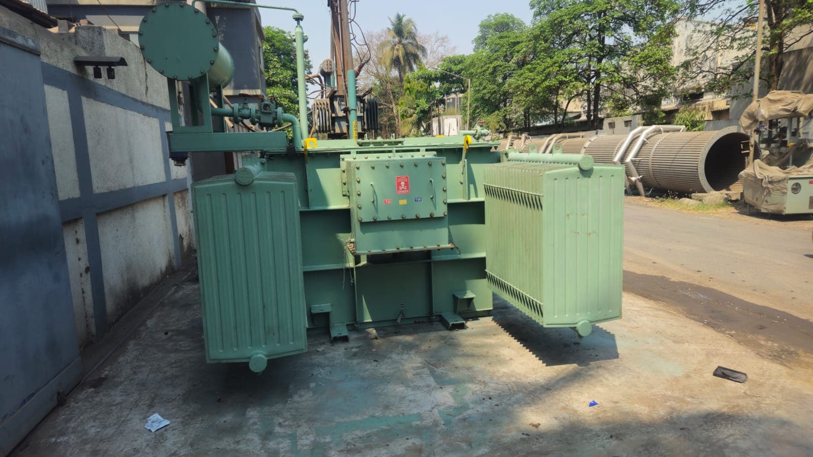
A power transformer sits between voltage levels further up: at a
substation, at a large plant intake, or between two parts of a network. It
feeds other transformers or a substantial single load rather than end
consumers, and it typically runs at a higher and steadier fraction of its
rating.
The consequence runs through loss economics.
Every transformer has two kinds of loss. No-load loss is the core loss —
it exists whenever the unit is energised, regardless of load, and it is set by
core material and geometry. Load loss is the copper loss, which rises with
the square of the current.
A distribution transformer spends most of its life lightly loaded, so no-load
loss dominates. It is energised 8,760 hours a year and it is paid for every
one of them, whether or not anybody is drawing power. This is why distribution
transformer design concentrates on the core.
A power transformer runs closer to its rating for longer, so load loss
dominates and the economics shift to the windings.
Specify one as if it were the other and you get a unit that is technically
functional and economically wrong.
Percentage impedance does two jobs. It sets the fault level that downstream
switchgear must interrupt, and it determines how load shares between units
running in parallel.
Lower impedance gives better voltage regulation but a higher through-fault
current. Higher impedance limits fault current at the cost of regulation.
If a transformer will run alongside an existing one, its impedance must match
closely. A mismatch means the two circulate current between themselves instead
of sharing load — both run hot, neither delivers its rating, and the cause is
rarely obvious from the outside.
Because a power transformer sits closer to the source, the fault current it can
see is higher, and the mechanical forces on the windings during a through-fault
scale with the square of that current. Clamping and bracing carry more of the
design effort than they do on a distribution unit.
Distribution units are almost always ONAN — Oil Natural, Air Natural. The oil
circulates by thermosiphon, the radiators lose heat to still air, and there is
nothing to fail.
Power transformers may be specified ONAN/ONAF, where fans raise the continuous
rating of the same tank when needed. That gives a dual rating, and it is worth
having where load is expected to grow, but it also introduces fans, controls
and a maintenance obligation that did not exist before.
Ask what the transformer is feeding:
- Feeding final consumers — a distribution transformer, optimised for
no-load loss.
- Feeding a substation busbar, a plant intake, or other transformers — a
power transformer, specified around impedance, load loss and short-circuit
withstand.
Then check three things before you commit:
- Load profile. Not the peak — the shape across a day. A unit that peaks
at 80% for two hours and sits at 20% for twenty is a different design
problem from one that holds 70% continuously.
- Parallel operation. If it will run with an existing unit, the impedance
and vector group are fixed for you by that unit, not chosen.
- Growth. Sizing for today's load and replacing in five years is usually
more expensive than one step up now. Sizing three steps up means paying
no-load loss on capacity you never use.
Whichever type the job needs, the routine test certificate is what turns the
specification into something verifiable. Ratio, winding resistance, insulation
resistance, no-load loss and load loss should all arrive with the unit. Keep
them — they are the commissioning baseline that every later maintenance reading
gets compared against, and without them you are guessing at whether a change is
real.
Related: Oil cooled distribution transformers ·
Power transformers ·
Understanding transformer losses